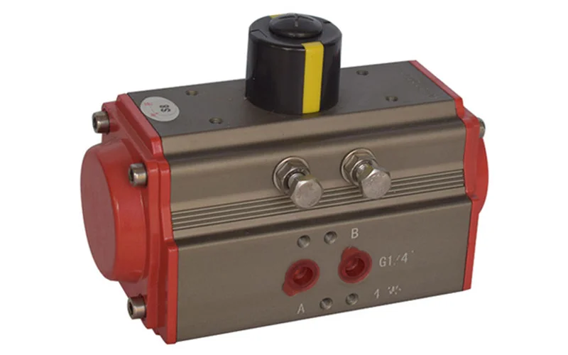
A single acting actuator uses fluid pressure to move in one direction and a restoring force to return in the other direction. In industrial pneumatic valve assemblies, that restoring force is commonly a spring. Compressed air drives one stroke, while stored spring energy moves the valve toward its configured failure position when air is released.
This guide focuses on pneumatic spring-return valve actuators. For engineers and buyers, the main task is to verify that both strokes can move the valve under the required conditions. A large air-stroke torque figure does not prove that the spring can complete the return stroke.
Key Takeaways
- Single acting means air drives one stroke and a spring drives the other; the failure direction depends on construction, not on the actuator family.
- Size the actuator at the minimum available air pressure, and check torque at air-start, air-end, spring-start and spring-end positions.
- A spring-return assembly can be fail-open or fail-closed; specify the required valve position and the failure event, not the actuator description.
- Accessories (solenoid, positioner, limit switches, speed control) determine whether the intended failure actually occurs in service.
- Spring housings contain stored energy; follow the manufacturer’s procedure during maintenance and commissioning.
How a Single Acting Actuator Works
In an air-to-open, spring-to-close assembly, supply air moves a piston or diaphragm against spring force. A linkage or drive mechanism transfers that motion to the valve stem or shaft. When the operating chamber is vented, the spring returns the mechanism toward the closed position.
An air-to-close, spring-to-open arrangement reverses the valve function. The correct version depends on the process requirement and the approved assembly configuration. Do not infer action solely from the appearance of the actuator housing.
Single acting actuators can produce linear motion for globe valves or rotary motion for ball and butterfly valves. Rotary mechanisms include rack-and-pinion, scotch-yoke and vane designs, each with its own output characteristics. For example, Rotork’s K-TORK range includes both spring-return and double-acting rotary vane configurations. This shows why the actuator’s mechanism and its operating action should be specified separately.
Single Acting Versus Double Acting
| Feature | Single acting with spring return | Double acting |
|---|---|---|
| Normal driving force | Air in one direction, spring in the other | Air drives both directions |
| Return on air loss | Spring action if the chamber can vent and the assembly is free to move | Depends on the complete pneumatic arrangement |
| Sizing checks | Air and spring output throughout travel | Output in both powered directions |
| Package considerations | Spring housing and stored energy | Air circuitry and any required backup system |
| Typical selection reason | Defined return position | Powered movement in both directions |
A double-acting assembly does not automatically hold its last position on loss of air. Loads, leakage and accessory configuration can move it. Conversely, the presence of a spring does not prove every failure scenario will produce the intended safe process condition.
For the broader choice of actuator technology, see Control Valve Actuator: Types, Sizing and Selection.
Selecting Fail-Open or Fail-Closed Action
Begin with the process consequence of losing the utility supply. A heating-medium valve may need to close to stop heat input, while a cooling-water valve may need to open to preserve cooling. Those are examples of decision logic, not universal instructions: the plant’s process design determines the required action.
Write down the expected result for each event:
- Loss of instrument air upstream of the local regulator.
- Loss of electrical power to the solenoid or positioner.
- Loss of the control signal while utility supplies remain available.
- A commanded shutdown during normal operation.
These events can follow different pneumatic paths. A blocked exhaust, incorrectly selected solenoid or engaged manual override can prevent the expected spring movement. “Fail closed” therefore belongs to the complete valve package and control arrangement, not just the actuator purchase description.
Torque and Thrust Sizing
Compare the full operating curves
For a rotary valve, collect the required breakaway, running and seating torque for the specified fluid, temperature and differential pressure. Include the effect of extended periods without movement when relevant. Compare those requirements with the actuator’s available output at corresponding positions.
Spring force changes as the spring compresses or expands, and the drive mechanism changes how that force becomes shaft torque. The lowest useful margin can occur away from the position with the highest published torque. Emerson’s FieldQ actuator product data demonstrates checks at air-start, air-end, spring-start and spring-end conditions.
Use the minimum air pressure available at the actuator during movement. A header reading of 6 bar does not justify sizing at 6 bar if filters, tubing and simultaneous demand can reduce local pressure to 4.5 bar. Confirm maximum supply pressure as well, since excessive actuator output can overload the stem or coupling.
Illustrative screening example
Suppose a valve requires 80 N·m to break open and 65 N·m to seat closed. For this example only, assume an agreed application factor of 1.25. The corresponding screening requirements become 100 N·m and 81.25 N·m.
An actuator providing 120 N·m at air-start but only 75 N·m at spring-end would fail that closing check, despite passing the opening check. Running torque and the rest of both curves must also pass. The factor is illustrative; obtain the actual selection factor from the valve and actuator suppliers for the application.
For linear valves, perform the equivalent thrust review. Include pressure unbalance, required seating force, packing friction, spring force and available diaphragm or piston force. Do not convert a rotary torque rating into a linear-valve selection without the appropriate mechanism and geometry.
Accessories and Commissioning
Choose a solenoid arrangement that pressurizes and vents the operating chamber as intended. A positioner may be needed for modulation, while limit switches or a position transmitter provide status feedback. Local filtration, pressure regulation, exhaust protection and speed controls should match the environment and response requirement.
Closing faster is not always better. Liquid systems may need a controlled travel time to limit pressure transients, while shutdown duties may impose a maximum time. Specify the required timing and verify it at realistic supply and load conditions.
The comparison Pneumatic Valves vs Electric Valves: Which Is Better for Your Process? provides context when utility availability or remote operation influences the package choice.
During an authorized commissioning test, verify actual valve direction, full travel, indication and response to each specified failure event. Record the local supply pressure and travel time. Confirm that manual overrides are returned to their required operating state. Spring housings contain stored energy, so maintenance must follow the manufacturer’s procedure.
Frequently Asked Questions
Does single acting always mean fail closed?
No. A spring-return assembly can be configured to fail open or fail closed, depending on its construction and mounting. Specify the required valve position and failure event explicitly. Verify the assembled package rather than relying on a general actuator description or a housing label.
Can a single acting actuator modulate?
Yes. A suitable actuator with an appropriate positioner can hold intermediate positions. Selection must account for friction, spring characteristics, available output and the required response. A package intended only for occasional on-off movement should not be assumed to provide the same positioning performance.
Can I select an actuator from valve size alone?
No. Two valves of the same nominal size can require different torque because of seat design, pressure, temperature and service conditions. Obtain valve torque or thrust data, define a justified sizing margin, and compare that requirement with the actuator’s output over both operating strokes.
Check both strokes at minimum supply, not just air-start. A single acting actuator is selected by comparing the valve’s full torque curve with the actuator’s output at air-start, air-end, spring-start and spring-end. The spring-end position often limits the closing stroke and is the most common reason a spring-return package fails in service.
Conclusion
A single acting actuator is selected as part of the complete valve package, not in isolation. Define the failure position first, then verify that the air stroke and the spring stroke can both move the valve at the minimum available supply and at every position along the travel.
For an inquiry, share the valve model, torque or thrust data, normal and design differential pressure, the minimum air pressure available at the actuator, the required fail action for each utility-loss event, the required travel time and the intended accessories. Jianeng Valve can use those inputs to review a single acting actuator as part of the complete automated valve assembly before commercial award.
Technical Sources
- Rotork, K-TORK light-duty fluid actuator range, accessed October 14, 2026.
- Emerson, FieldQ actuator product data sheet (release 2), accessed October 14, 2026.
Sources verified October 14, 2026.
Need Help Specifying a Single Acting Actuator?
Share the valve model, torque or thrust data, normal and design differential pressure, the minimum air pressure available at the actuator, the required fail action for each utility-loss event, the required travel time and the intended accessories. JIANENG Valve can review the assembled package and confirm whether the spring-end position still has sufficient margin at the minimum available supply.
Discuss Your Application