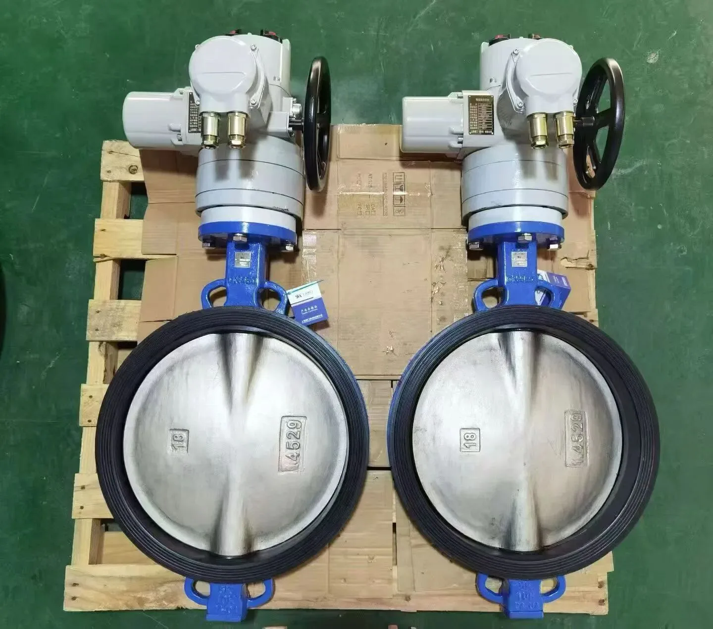
An electric valve actuator uses a motor, gears and control components to open, close or modulate an industrial valve. It is a practical automation choice where electrical power is available and instrument air is limited, but correct selection requires valve torque or thrust, motion type, speed, duty cycle, control signal, fail action and environmental protection.
The direct answer is that an actuator mounting flange and nominal torque label are only starting points. The complete assembly must deliver sufficient output at the required position and operating condition without damaging the valve, overheating the motor or failing the process response.
Key Takeaways
- Multi-turn, part-turn and linear electric actuators match different valve motions.
- Valve breakaway, running, dynamic and seating loads must be compared with actuator output across travel.
- On-off, inching and modulating duty have different motor and control requirements.
- Fail position may need a spring, capacitor, battery, UPS or external emergency power; standard motor actuators usually stay in place on power loss.
- ISO mounting interfaces define dimensions and reference loads, but the bracket, coupling and stem still require an engineering check.
What Is an Electric Valve Actuator?
An electric actuator converts motor rotation into valve movement through a gearbox, drive sleeve, output shaft or linear mechanism. Internal limit switches stop travel at the end positions, while torque or thrust sensing can protect the valve and confirm torque-seated closure. Local controls, remote commands and position feedback coordinate the assembly with the plant control system.
Electric actuators are used on ball, butterfly, plug, gate, globe and damper applications. The valve determines the required motion and load. A ball or butterfly valve normally needs part-turn output; a gate valve needs multi-turn output; and a globe control valve may need a linear actuator or a multi-turn actuator with a linear drive.
For a valve-level comparison, see Pneumatic Valves vs Electric Valves. Utilities, fail-safe action, speed and maintenance should be compared for the complete automated package. For a broader overview of pneumatic, electric and hydraulic choices, see the control valve actuator selection guide.
Multi-Turn, Part-Turn and Linear Types
Multi-turn actuator
A multi-turn actuator produces multiple output rotations and commonly drives gate or globe valves through a threaded stem nut. ISO 5210:2026 specifies attachment requirements for multi-turn actuators, including flange and driving-component dimensions and reference torque or thrust values.
Selection must distinguish torque-seated and position-seated valves. A wedge gate valve may close on torque after reaching its seat, while another valve stops at a calibrated position. Incorrect limit or torque settings can leave the valve leaking or overload the stem.
Part-turn actuator
A part-turn actuator rotates through 90 degrees or another limited angle for ball, butterfly and plug valves. It may use a worm gearbox or another reduction mechanism. ISO 5211:2026 specifies part-turn actuator attachment dimensions and reference torque values for interfaces and couplings.
Part-turn valve torque is not constant. Ball valves usually have breakaway and seating peaks; butterfly valves can add hydrodynamic torque that varies with disc angle and flow. The actuator output and gear ratio must cover the entire curve.
Linear actuator
A linear electric actuator converts motor rotation into stem thrust and travel. It can operate globe control valves, dampers or other linear devices. Check thrust in both directions, stem speed, travel, side-load alignment, seat load and the method used to stop at the end position.
| Motion type | Typical valves | Interface standard | Key selection checks |
|---|---|---|---|
| Multi-turn | Gate, globe | ISO 5210 | Stem nut engagement, seating method, number of turns |
| Part-turn | Ball, butterfly, plug | ISO 5211 | Breakaway, running and seating torque across travel |
| Linear | Globe control, damper | Stem connection | Thrust in both directions, speed, side-load, seat load |
How to Size an Electric Actuator
Step 1: Obtain exact valve load data
For rotary valves, request breakaway, running, dynamic and seating torque at the maximum differential pressure and relevant temperature. For linear valves, obtain pressure force, packing friction, seat load and total thrust in both directions. Use the exact trim, seat and packing configuration.
Step 2: Define the operating cases
Record normal and maximum differential pressure, fluid temperature, ambient temperature, flow direction, frequency of operation and required stroke time. Include low-voltage conditions when the power system allows them and check whether actuator output changes with voltage or frequency.
Step 3: Apply a documented margin
Add the agreed allowance for load uncertainty, seat aging, contamination and supply variation. Avoid selecting an actuator so large that its available torque or thrust can twist the stem, damage the seat or overload the mounting kit. Torque switches and current limits are protective devices, not substitutes for correct sizing.
Step 4: Check output across travel
Compare the valve requirement and actuator capability at the same positions. A headline output value may represent stall, maximum setting or one point in the travel. Confirm allowable continuous output, short-time output and gearbox rating.
Step 5: Verify speed and inertia
Stroke time affects the process and the mechanism. Fast closure can create surge, while slow movement may miss an emergency requirement. Large valves and gear trains have inertia; stopping accuracy and overrun must be considered with limit and torque settings.
The motorized ball valve vs motorized butterfly valve guide shows how valve size, capacity and torque influence the complete motorized-valve choice.
On-Off vs Modulating Control
On-off duty
An on-off actuator receives open and close commands and travels to calibrated end positions. Specify remote contacts, local selector, end-position feedback, running indication, fault output and interlocks. The controller should prevent simultaneous open and close commands.
Inching or positioning duty
Inching control uses short open or close pulses to adjust position. Frequent starts can heat the motor and contactors, so the permitted starts per hour and minimum rest time are important. Inching does not necessarily provide accurate closed-loop modulation.
Modulating duty
A modulating actuator receives an analog or digital command and continuously corrects position. It needs suitable motor duty, controller resolution, position sensor, deadband and mechanical backlash. State the expected number and size of movements per hour rather than writing only “modulating.”
Communication options may include 4–20 mA, voltage signals, discrete commands, fieldbus or industrial Ethernet. Define loss-of-signal action, local/remote priority, command source, feedback scaling and cybersecurity requirements at the control-system level.
Fail Action and Manual Override
Most conventional geared electric actuators stop in place when power is lost. If the process requires fail-open or fail-closed movement, the assembly may need a spring-return mechanism, capacitor or battery module, UPS, emergency generator or an electrohydraulic design. Each method has limits on stored energy, travel time, test frequency and maintenance.
Separate these scenarios:
- Loss of command signal
- Loss of control power
- Loss of motor power
- Communication failure
- Internal actuator fault
- Emergency shutdown command
A handwheel supports local operation during maintenance or loss of power, but it must include safe declutching and clear direction indication. Operators should not use excessive force or extensions to overcome a jammed valve. Local manual operation must be coordinated with electrical isolation and control-room status.
Electrical and Environmental Requirements
Specify supply voltage, phase, frequency, allowable variation, control voltage and power consumption. Confirm starting current, cable size, protective device, earthing, motor protection and terminal arrangement. IEC 61010-2-202:2020 provides safety requirements specific to electrically operated valve actuators and solenoids used in industrial process or discrete-control environments.
Environmental selection includes enclosure protection, corrosion category, ambient temperature, condensation, flooding, dust, vibration, solar exposure and hazardous-area classification. An outdoor location may require a space heater, drain or breather and sun shield. A high IP rating does not by itself prove corrosion resistance or suitability for immersion.
The mounting kit must transmit torque or thrust without excessive backlash, bending or misalignment. Check flange, coupling, key, stem engagement, bracket, fasteners and paint system. For large butterfly valves, review butterfly valve gear operation and selection because the electric actuator may drive an intermediate worm gearbox.
Commissioning Checklist
- Confirm valve moves freely before powered operation
- Verify supply voltage, phase and rotation
- Set open and closed travel limits
- Set torque or thrust limits using valve requirements
- Check local and remote commands
- Verify position feedback and end switches
- Test fail and loss-of-signal responses
- Measure stroke time
- Confirm manual override and declutching
- Record settings, firmware and communication address
- Test interlocks and emergency command logic
- Inspect coupling, bracket and fasteners after operation
Common Selection Mistakes
- Selecting by nominal valve size only
- Comparing valve peak torque with actuator output at another position
- Ignoring duty cycle and starts per hour
- Assuming power loss creates a fail-safe position
- Using limit switches to protect a torque-seated valve without torque control
- Oversizing until the actuator can damage the stem or seat
- Omitting low-voltage, ambient-temperature or enclosure checks
- Treating an ISO flange pattern as proof of complete mounting-kit strength
- Failing to document signal-loss and communication-failure behavior
Electric Valve Actuator Datasheet Checklist
- Valve type, size, travel and seating method
- Torque or thrust requirement across travel
- Maximum differential pressure and temperature
- Multi-turn, part-turn or linear motion
- On-off, inching or modulating duty
- Required stroke time and starts per hour
- Supply and control voltage, phase and frequency
- Input command, feedback and communication
- Fail action for each loss scenario
- Local controls and manual override
- Enclosure, corrosion and hazardous-area requirements
- Mounting flange, bracket, coupling and stem details
- Documentation, test and commissioning requirements
Frequently Asked Questions
What happens to an electric valve actuator when power fails?
Most geared motor actuators stop in their current position. A defined fail-open or fail-closed action requires stored energy or an alternate power source. Specify the required response, travel time and test method rather than assuming “electric” means fail-safe.
How do I choose actuator torque?
Use valve torque data for breakaway, running, dynamic and seating conditions at the actual differential pressure and temperature. Compare that curve with actuator output across travel, then apply a documented margin that does not exceed valve or mounting limits.
Can the same actuator be used for ball and butterfly valves?
Possibly, if motion, interface, torque curve, travel stops, speed, duty and environment all match. Ball and butterfly valves can have very different breakaway and dynamic torque even at the same nominal size.
What is the difference between on-off and modulating actuators?
An on-off actuator travels between end positions on discrete commands. A modulating actuator accepts a proportional command and repeatedly corrects intermediate position. Modulating service needs suitable motor duty, position feedback, controller resolution and backlash control.
Match the actuator to the valve, not the label. An electric valve actuator is selected from the valve’s torque or thrust curve across travel, the required duty cycle and the documented fail strategy. Comparing catalog labels alone almost always leaves a valve either under-driven or over-driven.
Conclusion
An electric valve actuator must be selected as part of the valve and control system. Motion type, torque or thrust, differential pressure, speed, duty cycle, fail strategy, power, signals, environment and mounting strength all affect reliability.
For an automated-valve inquiry, share the valve data, torque or thrust curve, operating cases, stroke time, duty, power, signal, fail response and enclosure requirements. Jianeng Valve can help review the valve-actuator interface and organize a complete electric actuation package before quotation.
Technical Sources
- International Organization for Standardization, ISO 5210:2026 — Multi-turn actuator attachments, accessed August 28, 2026.
- International Organization for Standardization, ISO 5211:2026 — Part-turn actuator attachments, accessed August 28, 2026.
- International Electrotechnical Commission, IEC 61010-2-202:2020, accessed August 28, 2026.
Sources verified August 28, 2026.
Need Help Specifying an Electric Valve Actuator?
Share the valve type, torque or thrust curve, differential pressure, stroke time, duty cycle, supply voltage, control signal, fail position and enclosure requirement. JIANENG Valve can help review the valve-actuator interface and organize a complete electric actuation package before quotation.
Discuss Your Application