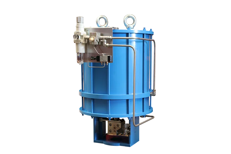
A control valve actuator converts pneumatic, electric or hydraulic energy into the linear thrust or rotary torque needed to position a valve. Correct selection requires more than matching the mounting flange: the actuator must move, control and seat the valve at the worst process condition while meeting fail action, speed, duty cycle, signal and environmental requirements.
The most important distinction is between force and control. A large actuator may move the valve, but stable modulation also depends on friction, positioner performance, deadband, linkage stiffness, resolution and controller tuning.
Key Takeaways
- Linear valves are sized by thrust; rotary valves are sized by torque.
- Worst-case shutoff differential pressure and minimum actuator supply are critical inputs.
- Pneumatic spring-return designs provide a defined fail direction; electric fail action may require a spring module, stored energy or backup power.
- A positioner improves command tracking but cannot correct an undersized actuator or damaged valve.
- Mounting standards define interfaces, not complete assembly strength, alignment or sizing.
What Does a Control Valve Actuator Do?
The actuator moves the closure member to a commanded position. On a globe valve, it pushes or pulls a stem and plug. On a ball, butterfly or eccentric rotary valve, it rotates a shaft through approximately 90 degrees or another defined travel. The actuator also supplies seat load or closing torque when shutoff is required.
The assembly can be on-off or modulating. On-off service uses discrete open and closed commands, often with limit switches and a solenoid or reversing starter. Modulating service receives a proportional signal and uses a positioner or internal controller to place the valve between its end positions.
Body style changes the mechanical load. Review control valve types used in industrial applications before comparing actuators only by nominal valve size.
Main Actuator Types
Pneumatic diaphragm actuator
A diaphragm actuator uses instrument air acting on a flexible diaphragm. A spring normally provides the opposing force and fail direction. These actuators are common on globe control valves because they offer simple linear motion, useful sensitivity and a direct relationship between air pressure, spring force and travel.
Travel and thrust are limited by diaphragm area, spring range and available air pressure. Large shutoff forces may require a larger housing, balanced trim or a piston design. Diaphragm material and ambient temperature must suit the installation.
Pneumatic piston actuator
A piston actuator uses air pressure on one or both sides of a piston. It can provide high thrust or torque in a relatively compact package. Single-acting versions use a spring or other stored-energy method for fail movement; double-acting versions use air in both directions and need a defined response to air loss.
Piston actuators are used on linear valves and with scotch-yoke or rack-and-pinion mechanisms on rotary valves. The mechanism changes the torque curve, so compare actuator output with the valve torque requirement across the full stroke.
Electric actuator
An electric actuator uses a motor, gearing and controls to produce multi-turn, part-turn or linear output. It can simplify installations without instrument air and can provide local controls, position feedback and digital communication. Selection must cover voltage, motor starts, duty cycle, speed, enclosure, ambient temperature and fail strategy.
The pneumatic valves vs electric valves comparison explains utility, response, fail-safe and lifecycle tradeoffs for complete automated valve packages.
Hydraulic and electrohydraulic actuators
Hydraulic actuators deliver high force density and can suit fast or high-load duties. Electrohydraulic packages use an electric motor and local hydraulic circuit, sometimes with spring or accumulator energy for fail action. They add fluid cleanliness, seal, leak, maintenance and temperature considerations.
Linear Thrust and Rotary Torque
Linear actuator thrust
Globe-valve actuator sizing commonly considers pressure force on the plug or unbalanced area, required seat load, packing friction, stem friction and any additional process or mechanical force. Direction matters: the critical case may be opening, closing or seating depending on flow direction and trim design.
Balanced trim can reduce pressure force but introduces balance seals, leakage paths and temperature limits. Never assume a balanced plug eliminates the need for a shutoff calculation.
Rotary actuator torque
Ball and butterfly valves need torque to break the seat, run through travel and reseat. Differential pressure, seat material, temperature, frequency, media buildup and time in one position can change the requirement. Butterfly valves may also experience dynamic torque from flowing fluid, especially during closure.
Actuator output is not constant for every mechanism. A scotch-yoke can deliver a different curve from a rack-and-pinion design, while pneumatic output changes with supply pressure and spring compression. Compare torque at each relevant angle, not only the headline maximum.
How to Size a Control Valve Actuator
- Define the valve and trim. Record valve type, size, pressure class, stem or shaft dimensions, travel, flow direction, trim style, seat material, packing and required leakage. Obtain the manufacturer’s thrust or torque data for the exact configuration.
- Define worst operating cases. Include maximum shutoff differential pressure, maximum and minimum temperature, minimum air pressure or voltage condition, flow direction and any emergency case. A normal operating pressure drop is rarely sufficient for final actuator sizing.
- Calculate required thrust or torque. For linear valves, sum the forces in the correct direction and include the specified seat load. For rotary valves, compare break, running, dynamic and seating torque across travel. Use the valve manufacturer’s method and document all assumptions.
- Apply an agreed sizing margin. The margin should cover uncertainty, friction growth, supply variation and service aging without overloading the stem, shaft, seat or mounting kit. Do not apply multiple hidden safety factors to both the valve data and actuator output.
- Check travel, speed and control. Confirm the actuator reaches the required stroke or angle, meets closing time and provides sufficient resolution. For modulating service, assess positioner, air capacity, motor control, deadband and frequency of movement.
General control valve sizing should be completed before actuator selection because valve size, trim, pressure drop and flow direction determine the mechanical load.
Positioners and Accessories
A positioner compares the command signal with measured valve position and adjusts actuator energy to reduce the error. Pneumatic, electro-pneumatic and digital positioners can improve response, overcome friction and provide diagnostics. IEC 60534-6-1 defines mounting details intended to support interchangeability of positioners on linear actuators.
Common accessories include:
- Air filter regulator
- Solenoid valve
- Limit switch or position transmitter
- Volume booster or quick exhaust
- Lock-up valve
- Manual override
- Local control station
- Partial-stroke test capability
Accessories must be selected as a system. A high-flow booster can make a valve fast but unstable if the positioner, tubing and controller are not coordinated. A solenoid used in a safety action must have the correct de-energized state and flow capacity.
Fail Action, Speed and Duty Cycle
Fail-closed, fail-open and fail-in-place describe the desired response to loss of air, power or signal, but those failures are not always identical. Document each scenario separately. A pneumatic actuator may fail on air loss through spring force while retaining its last command after signal loss if the control logic does not vent it.
Stroke time must match the process. Fast closure can limit inventory release but create surge or water hammer; slow closure may not meet shutdown requirements. Include valve volume, actuator volume, air pressure, tubing, solenoid Cv and hydraulic or motor speed in the review.
Duty cycle is especially important for electric actuators. A device suited to occasional isolation may overheat in continuous modulating service. State starts per hour, average travel, holding requirement, ambient temperature and expected control frequency.
Mounting and Interface Checks
ISO 5211 defines part-turn actuator attachment dimensions and reference torque values for interfaces and couplings. A compliant flange pattern does not guarantee that the bracket, coupling, stem key, bolting and alignment can carry the actual load.
Check mounting height, coupling engagement, backlash, shaft alignment, corrosion protection and accessibility. Avoid side loading on a linear stem. After assembly, calibrate travel stops and confirm that the actuator stops do not force the valve beyond its permitted seat position.
Force and control must be reviewed together. Sizing the actuator from valve diameter or peak actuator output is rarely enough. Confirm thrust or torque across travel at the worst differential pressure and minimum supply, then verify that the positioner, signal and accessories can deliver stable modulation at the required frequency.
Control Valve Actuator Datasheet Checklist
- Valve type, size, trim and travel
- Flow direction and maximum differential pressure
- Required shutoff and leakage
- Valve thrust or torque data by position
- Pneumatic, electric, hydraulic or electrohydraulic power
- Minimum and normal supply condition
- Fail response for air, power and signal loss
- On-off or modulating duty
- Signal, communication and feedback
- Required stroke time and duty cycle
- Positioner, solenoid, switches and air-set accessories
- Ambient temperature, enclosure and hazardous-area rating
- Mounting interface, bracket and coupling details
Common Selection Mistakes
- Sizing from valve diameter alone
- Using normal instead of shutoff differential pressure
- Comparing peak actuator torque with torque required at another angle
- Ignoring minimum air pressure or low-voltage conditions
- Choosing fail action without a process-safety review
- Applying excessive margin that overloads the valve
- Omitting duty cycle for an electric actuator
- Treating ISO mounting dimensions as proof of assembly strength
- Expecting a positioner to solve mechanical friction or backlash
Frequently Asked Questions
What is the difference between an actuator and a positioner?
The actuator supplies force or torque to move the valve. The positioner is a controller that compares the command with actual position and regulates actuator energy. A valve can have an actuator without a positioner for simple on-off service.
How much actuator safety factor is needed?
There is no universal factor. The project should define a margin based on valve data quality, process uncertainty, supply variation, friction, service aging and consequence of failure. Avoid stacking undocumented factors in multiple calculation steps.
Can one actuator size fit every valve of the same diameter?
No. Torque or thrust changes with valve style, trim, seat, packing, pressure, temperature, flow direction and shutoff requirement. Use data for the exact valve configuration and operating case.
Which actuator is best for a control valve?
The best choice depends on available utilities, load, fail action, speed, control frequency, environment, maintenance skills and lifecycle cost. Pneumatic diaphragm actuators are common for modulating globe valves; electric and piston designs can be better in other services.
Conclusion
A reliable control valve actuator is selected from valve load and process requirements, not mounting pattern or nominal size alone. Confirm thrust or torque across travel, worst differential pressure, minimum supply, fail action, speed, duty cycle, positioner and accessories as one engineered package.
Share the valve datasheet, operating cases, shutoff pressure, fail requirement, supply and control signal when requesting a review. Jianeng Valve can help match the control valve, actuator and accessories and document the sizing basis before quotation.
Technical Sources
- Emerson — Control Valve Handbook
- International Electrotechnical Commission — IEC 60534-6-1:1997
- International Organization for Standardization — ISO 5211 Part-turn actuator attachments
Sources verified August 28, 2026.
Need Help Sizing a Control Valve Actuator?
Share the valve type and size, trim, maximum shutoff differential pressure, flow direction, available air supply or voltage, fail action, stroke time and control signal. JIANENG Valve can help match the actuator, positioner and accessories and document the sizing basis before quotation.
Discuss Your Application