
A self operated temperature control valve regulates a heating or cooling medium using energy generated by its temperature-sensing system. A common arrangement combines a sensing bulb, capillary tube, actuator and control valve. Changes in sensed temperature move the valve without requiring an external electrical control signal or compressed-air supply.
For engineers and equipment buyers, this can be a useful approach to local temperature regulation. Selection depends on the heat load, valve capacity, required action, sensor location and acceptable temperature variation. A temperature setting alone is not enough to choose the valve.
Key Takeaways
- Define heating or cooling action first. The valve and actuator must be matched to the required direction of response to rising temperature.
- Size from heat demand, not from valve size. Convert the load into utility flow, then check that the selected valve passes it at the available differential.
- Valve travel develops over a temperature band, so a setpoint does not mean the process holds that exact value under all loads.
- Sensor position decides the quality of the control. A stagnant corner or a point dominated by the heat source gives poor regulation regardless of valve quality.
- Normal regulation and overtemperature protection are separate functions; a regulating setpoint is not a safety limit.
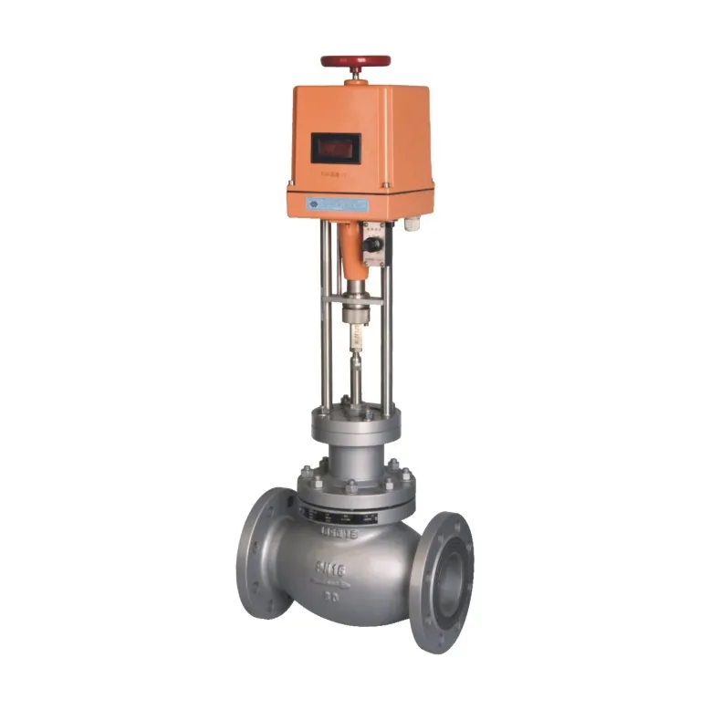
How a Self Operated Temperature Control Valve Works
In a common liquid-filled system, temperature changes cause the sensing fill to expand or contract. That change is transmitted through the capillary to an actuator, which moves the valve. Other sensing designs are also available, so confirm the offered system’s operating principle and limitations.
The sensed process fluid and the controlled utility fluid may be different. In a steam-heated tank, the sensor measures the tank contents while the valve regulates steam entering the heating coil. The sensor material must suit the tank fluid, and the valve materials must suit the steam conditions.
Spirax Sarco’s introduction to self-acting temperature controls explains the sensor-capillary-actuator arrangement and its proportional behavior. The practical point is that valve travel develops over a temperature band. A setpoint does not mean the process will hold that exact value under all loads.
This arrangement is often considered for local duties where a simple temperature response is sufficient. A process requiring rapid setpoint changes, detailed diagnostics, coordinated sequences or very tight temperature control may need an externally controlled valve and instrument system instead. Modulating Valve: How It Works and How to Select One covers that alternative in more detail.
Heating and Cooling Action
For a typical heating duty, a rise in sensed temperature should reduce the heating-medium flow. For a typical cooling duty, a rise in temperature should increase cooling-medium flow. The valve and actuator must therefore be matched to the required direction of response.
| Application question | Heating example | Cooling example |
|---|---|---|
| What is measured? | Temperature of a heated tank | Temperature of an oil cooler outlet |
| What does the valve control? | Steam or hot-water supply | Cooling-water supply |
| Desired response to rising temperature | Reduce heat input | Increase cooling flow |
| Main installation concern | Representative sensing and heat-transfer delay | Representative sensing and available cooling capacity |
Three-way arrangements can mix or divert utility flow, but their port function and sensing arrangement need separate review. For an explanation of the flow paths, see What Is a 3-Way Valve? Mixing and Diverting Flow.
Specify failure behavior separately from normal temperature action. A valve that closes as temperature rises does not necessarily close after capillary damage or loss of sensing fill. Request the manufacturer’s documented response for the exact assembly.
Capacity and Response Requirements
Convert the heat duty into utility demand
The valve must pass enough utility flow at the available pressure differential. Heat load, utility supply temperature or steam condition, and return conditions are therefore part of the sizing basis.
For an illustrative water-heating calculation, suppose a system needs 100 kW and the heating-water temperature falls by 10 K across the exchanger. Using an approximate water heat capacity of 4.18 kJ/(kg·K), the required mass flow is:
Using an approximate density of 1,000 kg/m³ for this screening example gives about 8.6 m³/h. Actual fluid properties vary with temperature, and this flow is not a valve size. The available valve differential pressure, minimum load and selected trim capacity must still be checked.
For steam, calculate demand using the appropriate steam and condensate enthalpy conditions. Do not apply the water example directly to steam. The guide Steam Control Valve: Sizing, Selection and Installation covers the steam data needed for valve selection.
Evaluate minimum load and thermal response
A large valve can meet startup demand but deliver too much heat with a small opening during normal operation. Ask the supplier to check both warm-up and steady-state conditions. Include the smallest sustained load and explain whether the process operates in batches or continuously.
Temperature response also depends on tank volume, mixing, heat-exchanger behavior and sensor delay. A slow response may come from the process rather than the valve. Conversely, a rapidly changing low-volume process may need faster sensing and control than the proposed self-operated system can provide.
Define an acceptable temperature band and a realistic load-change scenario. For example, specify a target near 60 °C, the permitted deviation and the expected change in demand. Do not turn a sensor’s adjustment range into an implied temperature-control accuracy.
Sensor and Capillary Installation
Position the sensor where it measures the temperature that matters to the process. In a tank, avoid a stagnant corner or a location dominated by the immediate heat source. In a flowing system, choose a representative measurement point with the required immersion and flow exposure.
A thermowell can allow sensor removal without opening the process directly, but it introduces another heat-transfer path and may slow response. Spirax Sarco’s guide to typical self-acting systems discusses thermowells, capillary arrangements and separate high-limit protection.
Confirm sensor length, connection, wetted material and access for removal. Route the capillary within the manufacturer’s bend-radius and temperature limits, protected from impact and hot surfaces. Do not assume it can be shortened, spliced or replaced independently of the matched sensing assembly.
For steam-heated equipment, drainage and available pressure across the condensate system also affect heating performance. A control valve cannot correct a heat exchanger that is unable to drain properly. Review the utility and condensate arrangement together before treating slow heating as a valve-capacity problem.
Selection Checklist
| Required information | What to specify |
|---|---|
| Control objective | Target temperature, acceptable band and heating or cooling action |
| Process behavior | Batch or continuous duty, thermal mass and load changes |
| Utility | Medium, supply and return conditions, available pressure differential |
| Capacity | Minimum, normal, maximum and warm-up heat loads |
| Sensor | Location, immersion, material, thermowell and connection |
| Capillary | Required length, routing and ambient conditions |
| Valve | Materials, connection, leakage requirement and allowable pressure-temperature envelope |
| Protection | Required response to sensing failure and separate high-limit functions |
After installation, verify the actual direction of response and compare the local temperature indication with the process measurement. Observe behavior at more than one load. If the process overshoots, investigate sensor lag, oversizing, poor mixing and residual heat input before changing the temperature setting repeatedly. Our self operated temperature regulator range covers the sensor and actuator arrangements most often supplied for these duties.
Frequently Asked Questions
Does a self operated temperature control valve need power?
A basic self-operated sensing and actuation assembly uses its own thermal response and does not need electrical power or instrument air for regulation. Additional indication, alarms or protective accessories may need utilities. Confirm the complete package rather than assuming every associated component is self-powered.
Can the same assembly control heating and cooling?
Only if the manufacturer’s design and configuration support the required action. Heating commonly requires less utility flow as temperature rises, while cooling commonly requires more. Specify the desired response and verify the approved valve-actuator combination instead of reversing connections or mounting without guidance.
Can it also provide overtemperature protection?
Normal temperature regulation and high-limit protection are separate functions. Where overheating can damage equipment, product or people, the process design may require an independent protective arrangement. Confirm the required trip action and reset behavior rather than treating the regulating valve’s setpoint as a safety limit.
Size from heat demand, not from valve size. A self operated temperature control valve is the last element in a chain that starts with the process heat load. Converting that load into utility flow, checking the available differential and confirming the sensor location removes most of the field problems seen with these valves.
Conclusion
A self operated temperature control valve should be sized around heat demand and installed around a representative sensor location. Once the utility flow, the direction of response and the sensor arrangement are settled, the remaining questions are the temperature band the process can accept and the protection required when sensing fails.
For an inquiry, share the process sketch, the utility medium and supply conditions, the load range, the target temperature and band, and the sensor and capillary requirements. Jianeng Valve can use those inputs to review a suitable self operated temperature control valve configuration before commercial award.
Technical Sources
- Spirax Sarco, Self-acting Temperature Controls, accessed October 29, 2026.
- Spirax Sarco, Typical Self-acting Temperature Control Valves and Systems, accessed October 29, 2026.
Sources verified October 29, 2026.
Need Help Specifying a Self Operated Temperature Control Valve?
Share the process sketch, the utility medium and supply conditions, the load range, the target temperature and acceptable band, and the sensor and capillary requirements. JIANENG Valve can review the heat duty, confirm the utility flow the valve must pass at the available differential, and check that the proposed sensing arrangement will regulate the process.
Discuss Your Application