A modulating valve adjusts its opening between closed and fully open to regulate a process variable such as flow, pressure, temperature or level. The controller changes the valve command as demand changes, and the actuator moves the valve to an intermediate position. Successful modulation depends on the complete control loop, including the sensor, controller, valve, actuator and process response.
For engineers and buyers, the key question is whether the assembly can control the required operating range. A valve that accepts an analog signal can still perform poorly if its flow capacity is too large, its actuator has excessive backlash or its trim is unsuitable for the fluid.
Key Takeaways
- A modulating valve is a control valve assembly used for intermediate-position regulation; the term emphasizes operating behavior, not a single body design.
- Successful modulation depends on the full closed loop: sensor, controller, valve, actuator and process response.
- Selection must cover minimum, normal and maximum flow cases with the corresponding differential pressure, not a single point.
- Actuator modulating duty, position feedback, command signal and fail action must be specified separately from the valve body and trim.
- A position problem and a process-tuning problem require different corrective action; record command, position and process measurement together.
How a Modulating Valve Works
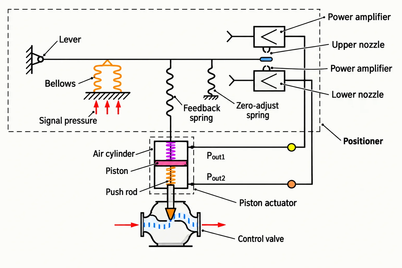
Consider a heat exchanger supplied with hot water. A temperature sensor measures the heated process outlet. When the measured temperature falls below its target, the controller can command the heating valve to open further. As heat input catches up with demand, the controller reduces the opening.
The process controller and valve positioner perform different jobs. The controller decides how much correction the process needs. A positioner uses stem or shaft feedback to make the actuator reach the commanded position. Emerson explains this position-feedback function in its valve positioner overview.
With a directly configured 4–20 mA travel signal, 4 mA may represent closed, 12 mA midpoint travel and 20 mA fully open. Reverse action and characterization can change that relationship. These values describe an illustrative configuration, not a universal wiring or calibration rule.
Half travel does not necessarily mean half flow. Flow also depends on the trim characteristic and pressure drop across the valve. Even a perfectly positioned valve cannot deliver a fixed flow percentage when the available differential pressure changes substantially.
Modulating Versus On-Off Operation
| Requirement | Modulating operation | On-off operation |
|---|---|---|
| Main purpose | Continuously adjust a process variable | Establish or stop a flow path |
| Command | Variable position demand | Open or close command |
| Position requirement | Repeatable intermediate travel | Reliable end positions |
| Actuator duty | Frequent corrections within its rated duty | Defined operating cycles |
| Main selection concern | Controllability across demand range | Isolation, travel time and cycling |
An on-off valve may use an electric or pneumatic actuator, just as a modulating valve can. The energy source does not define the control function. Likewise, adding a positioner to an isolation valve does not automatically make its flow characteristic suitable for stable process control.
A motor that is suitable for occasional full strokes may overheat if it makes frequent corrections. Specify starts per hour, operating time, ambient conditions and the required modulation duty. Manufacturer ranges such as Rotork’s precision modulating actuators distinguish continuous modulation from ordinary positioning duty. Check the exact offered model rather than applying one range’s capability to every electric actuator.
Selecting the Valve and Actuator
Match body style to the service
Globe valves offer a range of trim options for throttling. Characterized ball and eccentric rotary valves can combine rotary motion with useful flow characteristics. Butterfly valves offer compact construction and high capacity, but the useful control range and pressure-recovery behavior need application review.
The appropriate choice depends on fluid properties, required capacity, pressure drop, solids, leakage requirements and maintenance access. Use What Are the Different Types of Control Valves Used in Industrial Applications? to compare the basic body options before narrowing the specification.
Check every operating case
Prepare minimum, normal and maximum flow cases with inlet pressure, outlet pressure and temperature for each. Ask the supplier to report the predicted opening at those conditions. A valve selected only for maximum flow may operate very close to its seat during normal production, leaving little usable movement for small corrections.
For example, an illustrative water application might require 2, 8 and 12 m³/h at different production rates. Those three flows alone are insufficient for sizing. If the available valve differential pressure is 0.8 bar at normal flow but only 0.2 bar at maximum flow, the capacity calculation must use the corresponding pressure for each case.
The separate guide Control Valve Sizing: Cv, Kv, Pressure Drop and Selection explains the required input data. Also ask for checks on cavitation, flashing, noise and fluid velocity where relevant.
Specify mechanical and control interfaces
Actuator selection must cover thrust or torque throughout travel, using the minimum available supply and the worst credible pressure differential. For rotary assemblies, bracket stiffness and coupling backlash can affect response. For sliding-stem assemblies, alignment and packing friction matter.
Document command signal, feedback signal, supply voltage or air pressure, local controls and communication protocol. State the required actions after loss of command, loss of air and loss of electrical power separately. These events need not produce the same result.
Commissioning and Troubleshooting
Verify the assembly’s travel without relying only on the control-room display. During an authorized commissioning test, compare commanded position with measured stem or shaft position at several points. Check movement in both directions to reveal deadband or friction, then confirm the process response under controlled operating conditions.
| Observed behavior | What to investigate first |
|---|---|
| Command changes but position does not | Air or power supply, wiring, friction, positioner setup |
| Position tracks but process oscillates | Loop tuning, process delay, oversizing, pressure variation |
| Good response in one direction only | Linkage, packing friction, actuator forces, calibration |
| Normal load occurs near closed position | Excess capacity, trim selection, system pressure balance |
Avoid tuning the controller repeatedly to compensate for a sticking valve. A position problem and a process-tuning problem require different corrective work. Record the command, actual position and process measurement on the same time scale before deciding which component to adjust.
RFQ Checklist
Send the supplier the following information:
- Fluid, composition, solids and operating temperature range.
- Minimum, normal and maximum flow with corresponding upstream and downstream pressures.
- Controlled variable, expected load changes and required response.
- Body, trim, seat, packing, leakage and connection requirements.
- Available air or power, command signal and position feedback.
- Required failure actions, accessories and environmental conditions.
- Requested sizing calculation, predicted travel and actuator duty confirmation.
Frequently Asked Questions
Is a modulating valve the same as a control valve?
A modulating valve is a control valve assembly used for intermediate-position regulation. The phrase emphasizes operating behavior rather than a particular body design. Globe, characterized ball and suitable butterfly valves may all perform this function when their trim, actuator and controls match the process.
Does a modulating valve need a positioner?
Pneumatic modulating assemblies commonly use a positioner to correct travel errors. Electric assemblies may have their own position-control electronics. The requirement depends on actuator design and performance needs. Confirm how actual travel is measured and controlled rather than specifying a separate positioner for every assembly.
Can a modulating valve provide tight shutoff?
It can, if the selected seat, trim and actuator meet the specified leakage requirement at the required differential pressure. Modulation alone does not establish shutoff performance. State the applicable leakage test and conditions, and identify any separate isolation function needed for the system.
Select the assembly by operating range, not by signal type. A valve that accepts a 4–20 mA command does not automatically control the process. Verify capacity at minimum, normal and maximum flow with the actual differential pressure, then confirm actuator duty, position feedback and fail action for every loss scenario.
Conclusion
Select a modulating valve by its ability to control the full operating range, then verify the actuator and control interfaces. Half travel does not guarantee half flow, and a positioner cannot rescue a valve that is incorrectly sized or poorly trimmed for the fluid. Build the RFQ around the application risk and confirm the proposed configuration against a clear technical basis.
For an inquiry, share the fluid, minimum, normal and maximum flow with the corresponding pressures, the controlled variable and required response, the available power or air, the command and feedback signals, the required fail action for each loss scenario, and any environmental constraints. Jianeng Valve can review the operating conditions and help organize a practical selection discussion before quotation.
Technical Sources
- Emerson, Valve Positioners — Final Control, accessed October 7, 2026.
- Rotork, Precision Modulating Actuators (SM Series), accessed October 7, 2026.
Sources verified October 7, 2026.
Need Help Specifying a Modulating Valve?
Share the fluid, minimum, normal and maximum flow with the corresponding pressures, the controlled variable and required response, the available power or air, the command and feedback signals, the required fail action for each loss scenario, and any environmental constraints. JIANENG Valve can review the operating conditions and help organize a practical selection discussion before quotation.
Discuss Your Application