
Control valve sizing determines the flow capacity and valve configuration needed to control a real process. It is not the same as matching the valve's nominal size to the pipe.
A DN100 line can use a smaller control-valve trim when the required capacity, velocity, noise, cavitation, rangeability and mechanical checks support it. This guide explains the data, calculations and selection checks that turn a process requirement into a useful control valve datasheet.
Quick Answer: How Is a Control Valve Sized?
A control valve is sized by defining the fluid and all operating cases, establishing inlet and outlet pressure at each flow rate, calculating the required Cv or Kv with an accepted method, selecting a valve and trim that cover the range, and checking travel, velocity, choked flow, cavitation, flashing, noise, materials and actuator force or torque.
What Are Cv and Kv?
Cv and Kv are flow coefficients that describe valve capacity under defined reference conditions. Cv is commonly used with U.S. customary units, while Kv is commonly used with metric units. They allow engineers to compare different valve sizes and trims without treating nominal pipe diameter as the valve's capacity.
Cv = Q × √(SG / ΔP)
In this simplified liquid relationship, Q is flow in U.S. gallons per minute, SG is specific gravity relative to water and ΔP is valve pressure drop in psi.
The simplified equation helps explain the variables, but it does not replace the full sizing method when viscosity, piping geometry, vapor pressure, choking or non-turbulent flow matters. Kv uses cubic metres per hour of water and a 1 bar reference pressure drop. A common approximate conversion is Cv ≈ 1.156 × Kv; project calculations should use one consistent unit system and the factors required by the selected standard or software.
The official IEC 60534-2-1 standard page describes sizing equations for compressible and incompressible fluids under installed conditions. ISA maintains related ISA75.01 control valve sizing work.
Why Pressure Drop Controls Valve Sizing
A control valve creates a variable restriction, so its capacity depends on the pressure available across that restriction—not only on upstream pressure. Pump pressure may also be consumed by static head, equipment, pipe friction and fittings.
Pressure drop changes with flow. A datasheet containing only a maximum-flow case can hide poor control at normal or minimum flow. A useful sizing set normally includes:
- Minimum controllable flow
- Normal operating flow
- Maximum required flow
- Startup, cleaning or upset cases when they are genuine requirements
- Inlet and outlet pressure for each case
Too little allocated valve pressure drop can require a large Cv and leave the valve with weak authority over the system. Excessive pressure drop can waste energy and increase noise, cavitation or flashing risk. The correct allocation is a system-design decision.
Data Required for Control Valve Sizing
Fluid properties
For liquids, provide fluid name, composition, density or specific gravity, viscosity, vapor pressure and critical pressure when required. For gases, provide molecular weight or specific gravity, compressibility factor, heat-capacity ratio and temperature. For steam, state whether it is saturated or superheated and provide pressure, temperature and flow units.
Operating cases
| Parameter | Minimum | Normal | Maximum |
|---|---|---|---|
| Flow rate | Required | Required | Required |
| Inlet pressure | Required | Required | Required |
| Outlet pressure | Required | Required | Required |
| Temperature | Required | Required | Required |
Use absolute pressure where the gas-sizing method requires it, and label gauge and absolute values clearly. Confusing them can materially change a compressible-flow result.
Mechanical and control requirements
Add pipe size and schedule, connection standard, pressure class, body and trim preferences, leakage requirement, fail position, air supply or voltage, control signal and accessories. Describe the controlled variable—flow, pressure, level or temperature—and whether the loop needs fast response, tight turndown or stable low-flow control.
Liquid, Gas and Steam Sizing
Liquid sizing
Basic turbulent liquid sizing relates flow to Cv, specific gravity and the square root of pressure drop. Real selection also checks viscosity correction, reducers, vapor pressure, liquid pressure recovery and choked flow. High-recovery rotary valves and low-recovery globe designs behave differently after the vena contracta, so Cv alone cannot show whether cavitation will occur.
Gas sizing
Gas density changes as pressure falls through the valve. The calculation therefore uses absolute pressure, temperature, molecular properties, pressure ratio and expansion factors. Do not apply the simplified liquid equation to compressed air, natural gas or another compressible service.
Steam sizing
Steam is compressible and may be saturated or superheated. Required data normally includes mass flow, upstream pressure, downstream pressure and temperature or degree of superheat. Wetness, noise, erosion and downstream velocity can be important in letdown service, and the outlet pipe may need to be larger as specific volume increases.
Cavitation, Flashing and Choked Flow
Cavitation begins when local liquid pressure falls below vapor pressure, creating bubbles that collapse after pressure recovers. The collapse can cause noise, vibration and material damage.
Flashing occurs when downstream pressure remains below vapor pressure, so vapor persists as a two-phase, high-velocity stream. Liquid choked flow occurs when reducing downstream pressure further no longer produces the increase predicted by the basic square-root equation. Gas choking is associated with a limiting pressure ratio.
Possible responses include staged pressure reduction, anti-cavitation trim, a different valve style, revised pressure allocation, harder materials, downstream expanders or multiple valves. These measures require application analysis rather than a generic “severe-service” label. The Emerson Control Valve Handbook provides additional reference material on sizing, noise and selection.
Valve Opening, Rangeability and Installed Behavior
Compare the calculated Cv for every case with the selected valve's rated Cv across its travel. A valve that barely passes maximum flow at full travel has little margin. One that passes normal flow almost closed may be difficult to control and can expose a small trim area to high velocity.
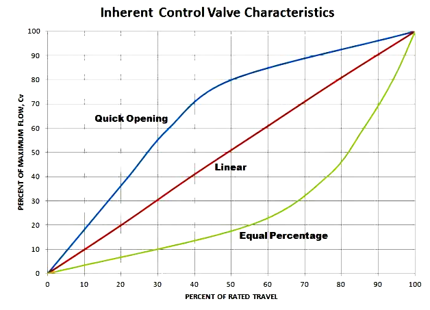
Inherent characteristic describes flow behavior at constant pressure drop. Common forms are linear, equal percentage and quick opening. Installed characteristic includes the way system pressure drop changes with flow. Equal-percentage trim can provide a more nearly linear installed response in many variable-pressure-drop systems, but the system curve must support that decision.
Published valve rangeability is not the same as process turndown. Installed low-flow performance can also be limited by friction, backlash, seat leakage, pressure variation, positioner performance and sensor resolution.
Eight-Step Control Valve Sizing Workflow
- Define all operating cases. Record minimum, normal and maximum cases using consistent units; add startup or upset cases only when they are real requirements.
- Confirm the pressure balance. Trace inlet and outlet pressures to pumps, vessels, static head, equipment and pipe losses, and identify which values are measured, calculated or assumed.
- Calculate required Cv or Kv. Use the appropriate IEC/ISA method and apply piping geometry, viscosity and other correction factors where required.
- Select valve style and trim. Compare globe, eccentric rotary, butterfly and characterized ball designs for capacity, controllability, recovery, solids, noise, leakage and maintenance.
- Check travel at every case. Tabulate predicted opening for minimum, normal and maximum flow and confirm useful control range and maximum-flow margin.
- Run severe-service checks. Review cavitation, flashing, choked flow, noise, velocity, vibration, erosion and temperature.
- Size the actuator. Check sliding-stem thrust or rotary break, run and seating torque using worst-case conditions and the actual minimum supply.
- Document the selection. Record body size, trim size, rated Cv/Kv, characteristic, travel, materials, leakage class, fail action and assumptions.
See JIANENG Valve's industrial control valve range when comparing available globe valve bodies and trims for different service conditions.
Illustrative Liquid Example
Suppose a water-like liquid must flow at 100 US gpm with an available valve pressure drop of 4 psi and specific gravity close to 1. The simplified screening relationship gives:
Cv = 100 × √(1 / 4) = 50
This is only a starting capacity. The engineer must still calculate the other operating cases and check travel, fluid properties, vapor pressure, reducer effects, velocity, cavitation, leakage and actuator requirements.
Common Control Valve Sizing Mistakes
- Selecting valve size only to match line size
- Using one flow case instead of minimum, normal and maximum
- Estimating valve drop without a system pressure balance
- Mixing gauge and absolute pressure in gas calculations
- Applying a liquid equation to gas or steam
- Adding large, undocumented safety factors to both flow and Cv
- Ignoring vapor pressure, cavitation, flashing and noise
- Sizing an actuator from normal rather than worst-case differential pressure
- Comparing quotations based on different trim, characteristic or leakage assumptions
Control Valve Datasheet Checklist
| Section | Minimum information |
|---|---|
| Fluid | Name, composition, phase, density, viscosity and vapor pressure |
| Cases | Minimum, normal and maximum flow, P1, P2 and temperature |
| Pipe | Size, schedule, material and connection |
| Function | Controlled variable, action and required response |
| Valve | Style, characteristic, leakage and materials |
| Actuator | Type, supply, fail position, signal and accessories |
| Review | Opening, velocity, cavitation, flashing, noise and torque or thrust |
| Records | Calculation method, software edition, inputs and assumptions |
Frequently Asked Questions
What is the difference between valve sizing and valve selection?
Sizing determines the required flow coefficient and checks capacity across the operating cases. Selection chooses the body style, trim, characteristic, materials, leakage class, actuator and accessories that can deliver that capacity safely and controllably.
Can a control valve be smaller than the pipe?
Yes. A control valve can be smaller when the required Cv, velocities, noise and mechanical checks allow it. Reducers must be included in the sizing analysis, and the final arrangement must consider support, drainage, maintenance and downstream expansion.
Why is an oversized control valve a problem?
An oversized valve may operate close to the seat at normal flow, where a small stem movement produces a large percentage change in capacity. This can cause hunting, poor low-flow control and trim wear.
Should Cv be calculated only at maximum flow?
No. Maximum flow checks capacity, while normal and minimum flow reveal controllability. Calculate every credible case and compare the required Cv with the selected trim curve.
What causes cavitation in a control valve?
Cavitation occurs when local liquid pressure falls below vapor pressure and then recovers, causing vapor bubbles to collapse. Risk depends on pressure levels, fluid vapor pressure, valve pressure recovery and geometry.
What information should be sent to a valve supplier?
Send fluid properties, minimum, normal and maximum flow, inlet and outlet pressure, temperature, pipe details, valve function, leakage requirement, material limits, actuator supply, signal and fail position. Ask the supplier to return calculated Cv/Kv, predicted opening, selected trim and severe-service checks.
Standards and Technical Sources
- IEC 60534-2-1:2011 — Sizing equations for fluid flow under installed conditions
- ISA75.01 — Control Valve Sizing Equations committee
- Emerson — Control Valve Sizing overview
- Emerson — Control Valve Handbook, Sixth Edition
Sources checked August 6, 2026.
Prepare a Control Valve Inquiry
Share the fluid, flow cases, inlet and outlet pressure, temperature, pipe details and control objective. JIANENG Valve can help organize the application data and review a proposed valve and actuator configuration before quotation.
Discuss Your Application