
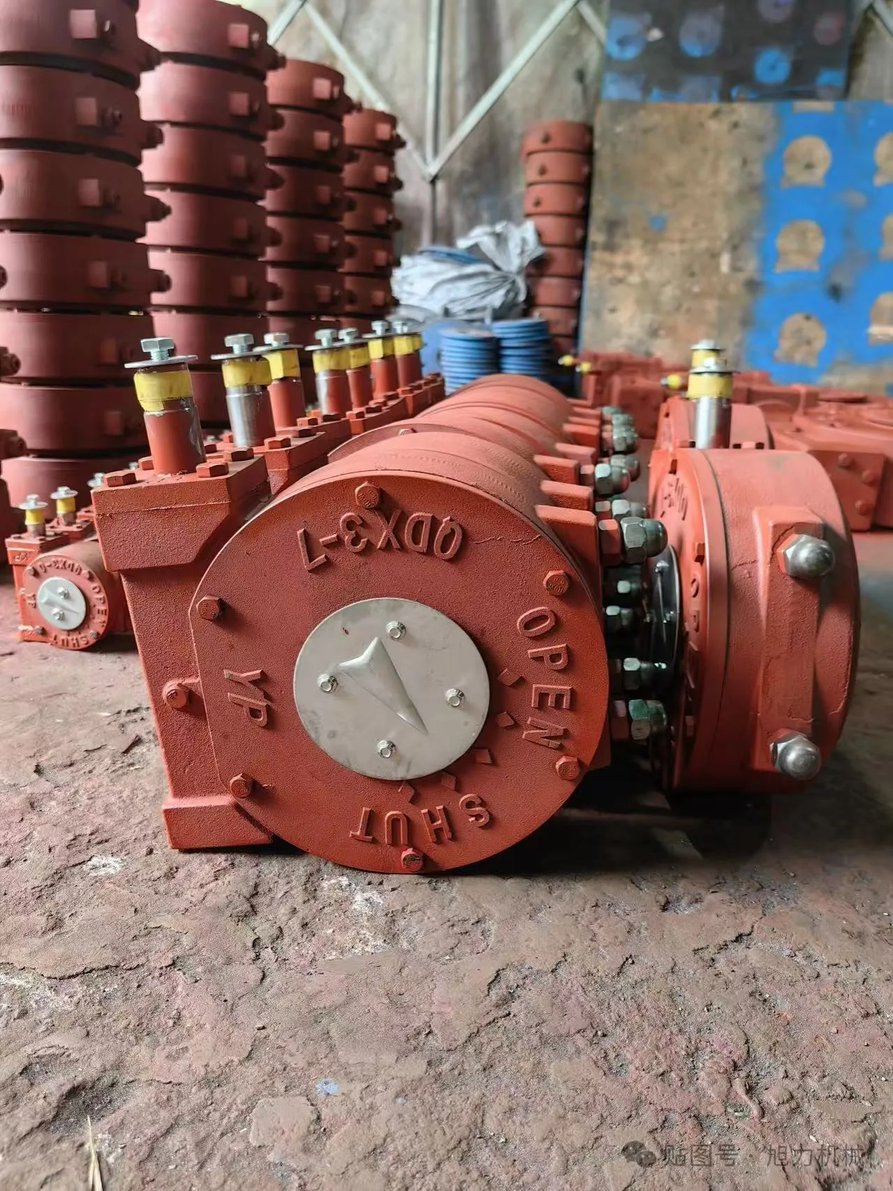
A butterfly valve gear type combines a quarter-turn valve with a manual gearbox, usually a worm gear and handwheel. The gearbox multiplies input torque so an operator can move a larger or higher-torque disc with manageable effort. It also slows travel and can help hold the disc at an intermediate position.
The gearbox must be sized for the valve's maximum required torque, not selected only by valve diameter. Seat material, differential pressure, temperature, flow direction, deposits and time in service can all change operating torque.
Quick Answer
Use a gear-operated butterfly valve when a lever would require excessive force, when slow controlled movement is preferred, or when manual intermediate positioning is needed. Confirm valve torque, gearbox output rating, ratio, efficiency, mounting flange, stem dimensions, rotation, stops, enclosure, handwheel effort and service factor.
How a Butterfly Valve Gearbox Works
Turning the handwheel rotates a worm shaft. The worm drives a sector or worm wheel connected to the valve stem. Multiple handwheel turns produce approximately 90 degrees of valve travel.
Mechanical advantage increases output torque but reduces speed. Gear ratio alone does not equal delivered torque because bearing, seal and gear friction reduce efficiency. Manufacturers rate allowable input and output torque; use those values rather than calculating from ratio alone.
Most units include adjustable open and closed stops. The stops limit travel but should not be used to force an incorrect disc position against the seat. The valve manufacturer's closed position and torque requirement control.
Some gearboxes are self-locking under specified conditions, meaning process torque is not expected to back-drive the handwheel. Do not treat this as a safety isolation or guaranteed position-holding function unless the manufacturer documents it for the actual load.
Gear-Operated vs Lever-Operated Butterfly Valves
A lever is convenient when torque is low and fast operation is acceptable. A gearbox is preferable when lever length or required force becomes impractical. Plant rules may also require gears above a defined size even if a lever could theoretically operate the valve.
| Factor | Lever | Gearbox |
|---|---|---|
| Travel | Fast quarter turn | Multiple handwheel turns |
| Operator effort | Increases quickly with torque | Reduced by mechanical advantage |
| Position indication | Handle position | Indicator plate or pointer |
| Intermediate setting | Notched plate, limited resolution | Finer manual positioning |
| Size and weight | Low | Higher |
| Common use | Small, low-torque butterfly valves | Larger or higher-torque valves |
For wafer type butterfly valves in small line sizes a notched lever is usually enough; once the seat, pressure class or duty cycle changes, a gearbox becomes the practical choice. See our butterfly valve for throttling guide for the control-side tradeoffs when intermediate positions matter.
Torque, Ratio and Handwheel Effort
Butterfly-valve torque is not one constant. It can include:
- Break-to-open torque after the disc has remained seated
- Running torque through intermediate angles
- Dynamic torque caused by flowing fluid
- End-to-close or seating torque
- Bearing and packing friction
Resilient-seated concentric valves may need significant seating and unseating torque. Offset designs reduce rubbing during much of travel but have their own dynamic and sealing forces. High temperature, swollen elastomers, corrosion, dry service and deposits can increase torque.
The gearbox output rating must exceed the required valve torque with an agreed service factor. At the same time, gearbox capacity should not be so high that an operator can damage the stem, disc or seat without noticing abnormal resistance.
Handwheel rim force depends on required input torque and handwheel radius. Procurement teams should request the predicted maximum rim effort rather than assume a handwheel is automatically ergonomic.
Rotork's 242-series information illustrates that quarter-turn gearboxes are published with defined output torque, ratios and application limits. Use the selected supplier's certified data for the actual unit.
Gearbox Components and Mounting Interfaces
Housing and enclosure
Cast iron, ductile iron, aluminum and fabricated housings are available. Outdoor, coastal, buried, washdown and fire-protection installations need different sealing and coating. Define ingress protection and corrosion environment.
Input and output
The input is normally a handwheel shaft. The output may be a keyed bore, square drive or removable drive sleeve. Confirm stem diameter, key, flats and engagement length.
Mounting flange
The gearbox attaches to a top flange or bracket. ISO 5211 mounting patterns are common, but matching bolt holes alone does not prove the stem and torque interface are correct.
Position indicator
The indicator should agree with actual disc position. Flow direction cannot always be inferred from the pointer, especially after field reassembly.
Travel stops
Stops are adjusted during assembly or commissioning. Tighten lock nuts and confirm seat closure without using the stop screw as a structural reaction for excessive torque.
Chainwheel or extension
Elevated valves may use chainwheels, floor stands or extension stems. These add loads, backlash and support requirements. The operator must remain accessible without exposing personnel to the pipeline or moving equipment.
How to Select a Butterfly Valve Gear Type
- Define valve and service. Provide valve design, size, pressure class, seat, temperature, differential pressure, medium and preferred flow direction. State whether the valve is for isolation or occasional throttling.
- Obtain torque data. Request break, run, dynamic and seating torque at worst-case conditions. Clarify whether published values already contain a safety factor.
- Select output rating. Choose a gearbox whose allowable output torque covers the design requirement. Check maximum permissible input torque and stem strength.
- Select ratio and handwheel. Balance acceptable handwheel effort against number of turns. Fast operation may need a lower ratio; high torque may need a higher ratio or larger wheel.
- Verify interface. Confirm mounting pattern, drive sleeve, key, stem height, rotation direction and indicator orientation. Check bracket stiffness if an adapter is used.
- Define environment. Specify indoor or outdoor location, ambient temperature, corrosion class, washdown, submersion risk and required enclosure. Add padlocking, chainwheel or limit switches where needed.
- Verify assembled operation. Cycle the complete valve and gearbox, set stops, confirm indicator and record handwheel turns. For throttling, verify the intended opening positions.
Operation, Maintenance and Troubleshooting
Operate the handwheel steadily. Sudden force, impact tools or extension bars can exceed gearbox and stem ratings. If torque rises sharply, stop and investigate deposits, line pressure, seat damage, stem corrosion or mechanical interference.
Periodic inspection should cover housing corrosion, fasteners, lubricant leakage, handwheel, indicator, stop screws, drive sleeve and mounting bracket. Follow the gearbox manufacturer's lubrication interval; some units are sealed for long service while others require maintenance.
Valve will not fully close
Check for solids at the seat, incorrect stop adjustment, drive-sleeve slip, stem twist or disc interference with the pipe. Do not simply tighten the closed stop.
Indicator disagrees with disc
The indicator or gearbox may have been assembled in the wrong orientation. Isolate and depressurize before verifying physical disc position.
Handwheel is unusually hard to turn
Confirm differential pressure and temperature. Look for seat swelling, bearing damage, corrosion, gearbox lubricant loss or an incorrectly sized unit.
Excessive backlash
Some backlash is inherent, but increasing lost motion can indicate gear wear, loose mounting, a worn drive sleeve or stem damage. Backlash matters more when the gearbox is used for manual throttling.
Common Mistakes
- Choosing gearbox size from nominal valve diameter only
- Multiplying input by ratio without accounting for rated efficiency
- Ignoring dynamic torque in flowing service
- Using a cheater bar on the handwheel
- Assuming matching ISO 5211 holes guarantee a correct drive
- Adjusting stops to compensate for seat or disc interference
- Omitting corrosion and ingress requirements
- Treating a manual gearbox as an automatic control actuator
RFQ Checklist
| Category | Required information |
|---|---|
| Valve | Type, size, class, seat, stem and mounting |
| Service | Medium, pressure, temperature and flow direction |
| Torque | Break, run, dynamic and seat values |
| Gearbox | Output rating, ratio, efficiency and rotation |
| Operator | Handwheel diameter, rim effort and number of turns |
| Interface | Flange, drive sleeve, key and bracket |
| Environment | Temperature, corrosion, enclosure and location |
| Options | Indicator, stops, locking, chainwheel and switches |
Application Scenarios
Large cooling-water isolation valve
A large resilient-seated butterfly valve may need a gearbox because seat breakaway torque and handwheel effort exceed the plant's manual-operation limit. The gearbox should be checked at maximum differential pressure and the lowest expected temperature, not just during a dry workshop test. If the line can flow while the valve moves, include dynamic torque and confirm the permitted flow direction.
Buried or outdoor installation
Buried service changes the operator arrangement. The project may require an extension spindle, surface box, position indicator and sealed enclosure. Outdoor gearboxes need corrosion protection and ingress resistance suitable for the environment. Drainage, condensation and lubricant temperature range are practical concerns. The torque path through extension components must be rated, aligned and protected against accidental overload.
Fire-water service
Fire-protection systems can require approved valve and gearbox combinations, supervisory switches and clearly visible position indication. Rotork's FB fire-protection butterfly-valve gearbox range is one example of a quoted assembly: a general industrial worm gearbox should not be assumed acceptable. Confirm the governing fire code, listing or approval, environmental enclosure and required open/closed monitoring for the complete assembly.
Manual throttling
A gearbox gives slower movement and finer hand positioning than a lever, but it does not make every butterfly valve a control valve. Where the application needs frequent automatic adjustment, a modulating control valve sized from Cv-versus-angle data usually provides a more appropriate control architecture. Use the butterfly valve for throttling guide when angular travel, disc characteristic and seat wear are part of the decision.
Factory and Site Acceptance Checks
Before installation, verify nameplate data, rotation direction, open and closed indicator positions, handwheel clearance and mounting fasteners. Operate the assembly through its full travel without process pressure and confirm that the stops halt gearbox travel at the required disc positions. Stops should protect travel limits; they should not force a misaligned disc into the seat.
Measure input torque or rim effort where the project requires it. Compare the result with the approved calculation and account for the difference between workshop and worst process conditions. Check backlash at intermediate positions if the gearbox will be used for manual throttling. Confirm that locking devices, chainwheels or position switches operate without interfering with travel.
At site, align the mating pipework and support the operator weight. Uneven flange pull can distort a resilient-seated valve and raise torque. Before pressurization, confirm disc clearance from flange bores, gaskets and adjacent fittings. After controlled pressurization, operate the valve only within the approved differential pressure and monitor for abnormal noise, movement or handwheel force.
Record gearbox model, ratio, output rating, drive sleeve, mounting orientation, stop settings and lubrication instructions. A replacement can then be selected from actual interface and torque data rather than appearance. Operators should be told not to add a cheater bar: excessive input can damage the gears, stem, disc or seat even when the handwheel still moves.
Maintenance Planning
Set inspection intervals from service severity, operation frequency and manufacturer guidance. Routine checks should cover loose mounting bolts, corrosion, water ingress, lubricant leakage, indicator alignment, abnormal handwheel effort and increasing backlash. A rarely operated isolation valve may benefit from an approved exercising program, but exercising must respect process and safety constraints.
When the handwheel becomes harder to turn, do not immediately adjust the stops or install a larger wheel. Isolate the cause by checking process differential pressure, seat condition, shaft alignment, bearings and gearbox condition. Record input effort at a repeatable operating condition. A gradual trend is more informative than an isolated subjective report.
For overhaul, preserve the drive-sleeve orientation and stop settings before disassembly. Replace seals, bearings or lubricant only with materials suitable for the gearbox and environment. After reassembly, repeat the travel, indication and torque checks. If gear teeth, worm shaft or housing are damaged, confirm whether excessive valve torque or external loads caused the failure before installing a replacement.
Keep the approved mounting drawing, torque calculation and spare-parts list with the maintenance record so future work uses the same technical basis.
After any valve-seat replacement, repeat the torque review because new seat material, compression or surface condition can change breakaway and seating torque. Do not assume the existing gearbox remains adequately rated merely because its mounting pattern still fits. Confirm maximum differential pressure and operating temperature before returning the assembly to service.
Frequently Asked Questions
Why use a gearbox on a butterfly valve?
A gearbox reduces the handwheel effort needed to rotate a higher-torque valve and slows the 90-degree movement. It can also provide finer manual positioning. The tradeoffs are added cost, weight, turns, backlash and maintenance.
What size butterfly valve needs a gearbox?
There is no universal diameter threshold. Required torque depends on pressure, seat, temperature, flow and valve design. Plant standards may set a size rule, but final selection should use maximum valve torque and acceptable operator rim effort.
Can a gear-operated butterfly valve throttle flow?
It can hold manual intermediate positions, but the valve must be suitable for throttling and sized from Cv/Kv-versus-angle data. A manual gearbox does not provide automatic process control, and backlash can limit repeatability.
How is gearbox ratio selected?
Select a ratio that keeps input and handwheel rim effort acceptable while avoiding impractically slow operation. Use manufacturer-rated input and output torque, which account for design limits and efficiency, rather than ratio alone.
Are worm gearboxes self-locking?
Some are described as self-locking within defined loads and conditions. Do not assume every worm gearbox will resist back-driving, vibration or process torque. Confirm the rating and use a separate locking or safety method where required.
What data should be supplied for a replacement?
Provide valve manufacturer and model, size, torque, stem drawing, mounting pattern, rotation, current gearbox details, handwheel orientation, environment and photographs. Verify the drive sleeve and closed position before operating the replacement.
Conclusion
A butterfly valve gear type should be selected as a torque-transmission assembly, not an accessory chosen by pipe size. Verify worst-case valve torque, gearbox ratings, ratio, rim effort, stem interface, stops and environment.
For a butterfly valve and operator inquiry, share the valve datasheet, differential pressure, temperature, seat material and mounting drawing. JIANENG Valve can help organize these inputs for a practical configuration review of our butterfly valves, with options for lever or pneumatic and electric actuators when automatic control is required.
Technical Sources
- Rotork — 242 Series Manual Quarter-Turn Gear Operators
- Rotork — FB Fire-Protection Butterfly-Valve Gearboxes
- American Petroleum Institute — API 609 Butterfly Valves Purchasing Information
- ISO — Valve Standards Catalogue
Sources verified August 25, 2026.
Need Help Selecting a Gear-Operated Butterfly Valve?
Share the valve datasheet, differential pressure, temperature, seat material and mounting drawing. JIANENG Valve can help organize the torque and interface data into a configurable butterfly valve and operator package.
Discuss Your Application