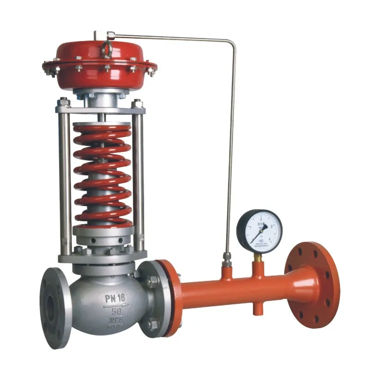
A back pressure regulator valve maintains pressure on its upstream side by opening when that pressure rises and restricting flow when it falls. It is used where a process needs a controlled pressure before the regulator, such as a recirculation loop, analyzer system or pressure-maintaining discharge line.
The first selection decision is therefore the location of the controlled pressure. A pressure-reducing regulator controls pressure after the valve. A back pressure regulator controls pressure before it. Interchanging these functions can leave a system unable to meet its intended operating condition.
Key Takeaways
- Decide first whether the controlled pressure sits upstream or downstream of the valve; the answer determines which device is correct.
- A back pressure regulator holds pressure only while a supply source and a usable downstream pressure differential exist; it cannot create pressure by itself.
- Size the regulator at the least favorable differential, which is usually the highest return-line pressure, not the easiest outlet condition.
- Expect accumulation: controlled upstream pressure rises as required flow increases, so the pressure-flow curve matters more than a single rating point.
- Normal pressure control and overpressure protection are separate duties. Do not accept a regulating valve as a relief device unless that configuration is explicitly approved.
How a Back Pressure Regulator Valve Works
The regulator compares upstream pressure with the force or loading pressure that establishes its setting. As upstream pressure rises, the regulating element opens a discharge path. As that pressure falls, the element moves toward closed to retain pressure upstream.
Direct-acting designs transmit the sensing force to the regulating element. Pilot-operated designs use a pilot circuit to position the main valve. The appropriate arrangement depends on capacity, required pressure stability, pressure differential and medium. Pilot operation can help where the required capacity or stability is difficult to obtain from a simple direct-acting arrangement, but the label “pilot operated” does not guarantee stable control under every load condition.
The regulator cannot create upstream pressure without a source of fluid and energy. It also needs a downstream path capable of accepting the discharged flow. If the downstream system pressure approaches the upstream target, the available driving pressure falls and the regulator may be unable to pass the required flow.
In a recirculating liquid loop, for example, the valve may discharge surplus flow to a return line while maintaining pressure ahead of it. The return-line pressure is part of the sizing calculation. Describing that outlet simply as “return” hides information the supplier needs.
Back Pressure, Reducing and Relief Functions
| Device or function | Controlled or protected location | Typical behavior |
|---|---|---|
| Pressure-reducing regulator | Downstream process | Opens further when downstream pressure falls |
| Back pressure regulator | Upstream process | Opens further when upstream pressure rises |
| Pressure-relief device | Protected equipment or system | Relieves an overpressure event according to its specified duty |
| Check valve | Direction of flow | Restricts reverse flow according to its design |
A back pressure regulator is not a check valve. Its normal job is pressure regulation, so reverse-flow protection must be assessed separately when needed.
Backpressure control and relief can appear in the same manufacturer’s product family. For example, Emerson’s Fisher Type EZR is described as a pilot operated pressure relief valve or backpressure regulator, used as a relief valve for overpressure protection in city gate service and as a backpressure regulator in commercial and industrial applications. That does not make every back pressure regulator a suitable protective relief device. The approved configuration, capacity, setpoint behavior and applicable requirements must match the intended function.
In a process specification, identify the normal control duty and protective duty separately. This prevents a routine pressure-maintaining valve from being purchased as an assumed substitute for a properly specified overpressure-protection system.
Sizing and Selection
Define the pressure target and permitted variation
State the required upstream setting and the pressure band the process can tolerate as flow changes. Include minimum, normal and maximum downstream pressure. Label gauge and absolute pressures explicitly, especially for gas calculations.
Back pressure regulators can exhibit accumulation: the controlled upstream pressure rises as the required flow increases. Swagelok’s technical explanation of back pressure regulators discusses this behavior. Request the actual pressure-flow curve and compare it with the permitted operating band.
Check flow at the least favorable differential
Consider an illustrative process requiring an upstream pressure of 5 bar(g), with 2 m³/h normal flow and 6 m³/h maximum flow. If return pressure can vary from 1 to 4 bar(g), the available differential can change from 4 to 1 bar at the nominal upstream target.
The supplier must check maximum flow at the high return pressure, not just at the easiest 1 bar(g) outlet condition. Minimum flow also needs review for stable regulation. These example values illustrate the input relationship and are not a proposed regulator size.
For liquids, evaluate density, viscosity, vapor pressure, cavitation and flashing where applicable. For gases, provide temperature, composition or molecular properties, and the required flow reference conditions. The general guide Control Valve Sizing: Cv, Kv, Pressure Drop and Selection explains why flow and pressure data must be paired.
Select materials and sealing performance
Check the body, trim, sensing diaphragm or piston seals, and seat against the actual medium. Include cleaning fluids, moisture and contamination. A pressure rating does not establish chemical compatibility, and a compatible body does not establish seat durability. Our corrosion-resistant valve range covers common material upgrades when the medium requires them.
Describe whether the process can tolerate leakage when flow demand stops. If a regulator leaks through its seat, upstream pressure may decay, but other process leak paths can produce the same symptom. Specify the required test or acceptance criterion so that supplier and purchaser evaluate the same behavior.
Installation and Troubleshooting
Install the regulator in the intended flow direction and connect any external sensing line at the location required by the manufacturer. Ensure that the sensing point represents the upstream process pressure to be controlled. A long or restricted impulse line can delay the signal or cause it to differ from the process condition.
Plan where the discharge goes. Depending on the medium, it may need a closed return, recovery system or another engineered destination. Include outlet backpressure from that system in the selection. Provide access for inspection and maintenance without changing the sensing arrangement during routine service.
Where a reducing regulator and back pressure regulator operate in the same system, coordinate their settings and the pressure loss through the intervening process. Two independent regulators trying to establish incompatible conditions can interact. Resolve the pressure balance instead of repeatedly adjusting both devices.
| Symptom | Initial checks |
|---|---|
| Upstream pressure exceeds the target at high flow | Capacity, downstream pressure, restrictions and accumulation |
| Pressure oscillates | Sizing, interacting controls, sensing delay and variable load |
| Pressure decays with the regulator nominally closed | Seat contamination, seat damage and other system leak paths |
| Pressure does not build | Source capacity, bypasses, orientation and setpoint range |
If the process instead needs remote pressure setpoint changes or integration into a wider control strategy, an instrumented valve package may be appropriate. Control Valve Actuator: Types, Sizing and Selection outlines the actuation and interface questions for that alternative.
RFQ Checklist
Provide the fluid and phase, upstream pressure target and tolerance, downstream pressure range, flow cases, temperature, connection standard and wetted-material requirements. Add the discharge arrangement, sensing location, required shutoff performance and any separate protective requirements. Request capacity calculations and pressure-flow data for the actual operating envelope.
Our self-operated and pilot operated regulator range covers the main body and diaphragm arrangements most often used for these duties.
Frequently Asked Questions
Can a back pressure regulator increase pressure?
It can retain upstream pressure by restricting discharge, but it cannot generate pressure without a supply source. If upstream supply is inadequate or another flow path remains open, closing the regulator may not establish the target. Check the complete pressure and flow balance of the system.
Does it maintain a constant pressure difference?
An ordinary back pressure regulator controls upstream pressure relative to its sensing reference. That is different from maintaining a fixed differential between two process points. If differential-pressure control is required, specify both sensing locations and the required differential rather than ordering by a general regulator name. Pressure Independent Control Valve: PICV Selection Guide covers the related case where valve authority is held constant as the differential changes.
Can it serve as the only relief protection?
Only if the exact device and configuration are specified and accepted for that protective duty. A normal pressure-control function does not establish relief capacity or qualification. The system designer must define the failure cases and protection requirements independently of the routine operating pressure target.
Name the controlled pressure location first. Most selection errors on back pressure regulators start with the wrong device function rather than the wrong size. Confirm whether the process needs pressure held before or after the valve, then apply the flow, differential, material and protection requirements to that function.
Conclusion
A back pressure regulator valve works best when its upstream target, outlet conditions and flow range are clearly defined. Once the function is correct, the remaining decisions are practical: check capacity at the least favorable differential, review accumulation across the flow range, match materials and seats to the medium, and keep normal pressure control separate from emergency overpressure protection.
For an inquiry, share the fluid and phase, the upstream pressure target and tolerance, the downstream pressure range, the flow cases, the discharge destination and the sensing location. Jianeng Valve can use those inputs to review the pressure-control arrangement and valve specification before commercial award.
Technical Sources
- Emerson, Fisher Type EZR relief valve or backpressure regulator, accessed October 21, 2026.
- Swagelok, Tech Talk: Back Pressure Regulators, accessed October 21, 2026.
Sources verified October 21, 2026.
Need Help Specifying a Back Pressure Regulator?
Share the fluid and phase, the upstream pressure target and tolerance, the downstream pressure range, the flow cases, the discharge destination, the sensing location and any separate protective duty. JIANENG Valve can review the pressure-control arrangement and check whether the regulator holds its target at the least favorable differential, not only at the easiest outlet condition.
Discuss Your Application