
A butterfly valve for throttling can be a practical control element when the service accepts rotary-valve behavior, moderate pressure drop and a carefully sized operating range. It is compact, relatively light and available in large sizes. However, partially opening any isolation butterfly valve does not automatically create stable process control.
The valve must be selected for modulation, not just shutoff. Disc design, seat, pressure recovery, available pressure drop, actuator, flow characteristic and expected opening range determine whether the result will be controllable or destructive.
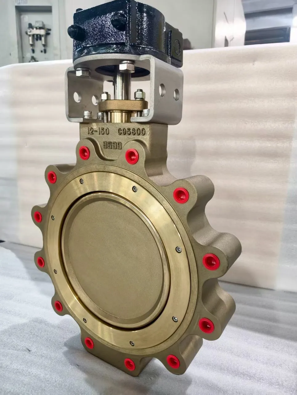
Quick Answer: Can a Butterfly Valve Throttle?
Butterfly valves can throttle clean liquids and gases when they are correctly sized and operated within a suitable angle range. Avoid selecting by line size alone. Check required Cv at minimum, normal and maximum flow; cavitation or noise; disc and seat velocity; actuator torque; leakage; and whether a globe or V-port valve would give better low-flow control.
How a Butterfly Valve Throttles Flow
A butterfly valve rotates a disc in the flow path. At the fully open position, the disc remains in the stream but offers a relatively large passage. As the disc closes, projected area increases, the restriction becomes stronger and pressure drop rises.
The relationship between disc angle and flow is nonlinear. Near closed, a small angular movement can create a large percentage change in the remaining flow area. Near fully open, additional rotation may produce little useful capacity change. The most controllable range depends on valve geometry and the installed system.
Throttling also creates asymmetric forces on the disc and shaft. Dynamic torque can change with angle, velocity and pressure direction. An actuator sized only for seating torque may not control the disc steadily at intermediate positions. The valve, actuator and positioner must be evaluated as one control assembly.
When Is a Butterfly Valve Suitable for Throttling?
Typical candidates include cooling water, treated water, HVAC circulation, low-pressure air, general utility services and large pipelines where a globe valve would be heavy or expensive. A butterfly valve is more likely to work well when:
- Minimum flow does not require operation extremely close to closed
- Pressure drop is moderate
- The fluid is clean enough for the selected seat and bearing arrangement
- Required leakage and temperature fit the design
- The actuator can hold intermediate positions
- The process does not demand very high rangeability
Use extra caution with cavitating liquids, flashing service, abrasive slurry, entrained solids, high acoustic noise, severe vibration, very high temperature or tight low-flow control. These services may require an offset severe-service design, special trim or a different control valve style.
Butterfly Valve Designs for Control
Concentric resilient-seated valve
The shaft and disc are centered, and the disc interferes with a resilient liner or seat throughout part of its travel. This design is economical and common in water service. It can provide modulating duty in appropriate conditions, but continuous partial opening may increase local seat wear.
Double-offset high-performance valve
Two offsets move the disc away from the seat earlier during opening, reducing rubbing. High-performance butterfly valves are used at higher pressure or temperature than many concentric designs and can provide improved throttling capability when properly sized.
Triple-offset valve
A third geometric offset creates a cam-like seating action. Triple-offset valves commonly use metal sealing elements and are considered for higher temperature, critical isolation and demanding services. "Triple offset" does not by itself guarantee a control characteristic, leakage class or freedom from cavitation; those requirements still need documentation.
Eccentric rotary control valve
Some rotary control valves resemble butterfly valves but use an eccentric plug or contoured disc developed specifically for modulation. They may provide better characteristic, seating and severe-service options than a general-purpose isolation butterfly valve.
API Standard 609 covers double-flanged, lug, wafer and butt-welding butterfly-valve configurations and includes design, material, pressure-temperature and testing requirements. API's current standards plan lists the tenth edition published in May 2026. A product standard defines construction and testing scope; it does not replace application sizing.
Disc Angle, Flow Characteristic and Installed Control
Manufacturers publish rated Cv or Kv versus disc angle for a specific valve size and design. Use that curve rather than assuming capacity is proportional to angle. The inherent characteristic is measured under approximately constant valve pressure drop. In an operating system, pressure drop changes as flow changes, so the installed characteristic can differ. Pumps, control valves, pipe friction and equipment all influence the result.
Avoid treating the final few degrees near closed as an ordinary control range unless the manufacturer's data and service analysis support it. High velocity through a narrow opening can damage a resilient seat, erode the disc edge or cause vibration. Operation too close to fully open can also reduce control authority because angle changes have little effect. For a deeper look at flow-versus-opening curves, see our guide on control valve sizing with Cv and Kv calculations.
Sizing, Pressure Drop, Cavitation and Noise
Start with minimum, normal and maximum flow. For each case, define inlet pressure, outlet pressure, temperature and fluid properties. Calculate required Cv or Kv using the correct liquid or gas method, then compare it with the angle-capacity curve.
For liquids, local pressure may fall below vapor pressure as flow accelerates around the disc. If pressure recovers downstream, collapsing bubbles can cause cavitation. A high-recovery valve can be more sensitive to this effect than a low-recovery globe design.
For gases, high velocity and pressure ratio can create aerodynamic noise and choked flow. The valve and downstream pipe should be checked together. Do not solve noise simply by specifying thicker pipe or a slower actuator.
| Check | What to verify | Why it matters |
|---|---|---|
| Disc angle | Predicted angle at minimum, normal and maximum flow | Confirms operation in a stable, controllable range |
| Velocity | Valve and downstream-pipe velocity at each case | High velocity can erode seats and generate noise |
| Cavitation | Liquid pressure versus vapor pressure across the disc | Cavitation damage can destroy seats and downstream piping |
| Choked flow | Gas pressure ratio and outlet velocity | Choking limits capacity and may require noise treatment |
| Dynamic torque | Torque at intermediate angles under flowing conditions | Actuator must hold position, not just open and close |
| Flow direction | Preferred shaft-to-seat orientation | Incorrect direction can increase torque and reduce shutoff |
Actuator and Positioner Selection
Manual levers and gearboxes are useful for occasional positioning but do not create automatic closed-loop control. Modulating service normally uses a pneumatic or electric actuator with suitable intermediate-position capability.
A pneumatic actuator usually needs a positioner to translate the control signal into stable shaft position. Define signal, air supply, fail action, travel stops, feedback and required response. A spring-return actuator may need substantially different sizing from a double-acting unit.
An electric modulating actuator should have a suitable duty rating, positioning resolution, control input, feedback and protection enclosure. Frequent corrections can overheat an actuator intended only for occasional open-close service.
Torque analysis should cover breakaway, running, dynamic and seating torque at the worst pressure and temperature. Apply an agreed safety factor without making the actuator so large that the shaft or seat can be overloaded. Compare actuator types further in our pneumatic vs electric valve actuator comparison.
How to Select a Butterfly Valve for Throttling
- Define the control objective. State whether the loop controls flow, temperature, pressure or level. Record required response and acceptable variation. A vague requirement to "adjust flow" is not enough.
- Build operating cases. Provide fluid, flow range, P1, P2 and temperature for minimum, normal and maximum conditions. Include vapor pressure, density and viscosity for liquids or molecular properties for gases.
- Choose the design family. Compare concentric, double-offset, triple-offset and purpose-designed rotary control valves. Evaluate seat temperature, leakage, corrosion, solids and maintenance.
- Size from capacity curves. Calculate required Cv/Kv and map each case to disc angle. Select a size that uses a stable angle range and retains credible maximum-flow margin.
- Check severe-service limits. Review cavitation, flashing, noise, velocity, vibration and erosion. Ask the supplier to document any limits on continuous throttling angle.
- Size the actuator package. Confirm torque, supply, signal, fail position, positioner, switches, manual override and mounting interface. Verify the valve, shaft and actuator as one assembly.
Butterfly Valve vs Other Throttling Valves
| Factor | Butterfly valve | Globe control valve | V-port ball valve |
|---|---|---|---|
| Size and weight | Compact, favorable at large sizes | Heavier | Moderate |
| Capacity | High for size | Lower for size | High |
| Low-flow control | Often limited | Generally strong | Good with characterized port |
| Pressure recovery | Relatively high | Lower | Relatively high |
| Solids handling | Design dependent | Trim can plug | V-port may suit some solids |
| Large-line economics | Often favorable | Can be costly | Application dependent |
This table is a screening guide, not a substitute for sizing. Specific valve geometry and trim can change the result. For detailed guidance on globe-style throttling, see our throttling valve selection guide.
Application Scenarios
Cooling-water temperature control
A cooling-water butterfly valve often operates with moderate pressure drop and a wide line size, which can make a characterized butterfly valve attractive. The sizing study should include the clean-exchanger condition and the higher system resistance expected after fouling. If the valve is sized only for the maximum design flow, it may spend normal operation close to the seat where small shaft movements create large relative flow changes.
Pump discharge and bypass control
On a pump discharge, the valve and pump curve interact. Closing the valve raises system resistance and moves the operating point; it does not simply subtract a fixed pressure. Confirm the pump's allowable operating region, minimum flow and potential for recirculation heating. A bypass valve may see high differential pressure at low flow, so cavitation and noise can be more severe than the large pipe diameter suggests.
Air and low-pressure gas service
Large butterfly valves provide substantial capacity, but compressible-flow calculations must use absolute pressure and the correct gas properties. Check outlet velocity, aerodynamic noise and choking. A disc that appears only partly closed can still create a strong jet. Also review whether the shaft seals and seat leakage requirement are appropriate for the gas.
Slurries and particle-bearing liquids
Solids can erode the disc edge and seat or collect in low-velocity areas. A valve suitable for clean water is not automatically suitable for abrasive slurry. Describe particle size, concentration, hardness, tendency to settle and required flushing. The selection may favor an offset geometry, different seat system or another valve style, but that decision needs manufacturer application limits.
Across all four scenarios, request predicted opening, velocity and torque at minimum, normal and maximum cases. The result should show not only that the valve can pass peak flow, but that it can control the everyday operating range without continuously occupying an unstable or damaging angle.
Commissioning and Performance Review
- Verify disc position against the actuator indication, positioner feedback and control-system signal
- Stroke the assembly slowly and confirm that mechanical stops do not prevent the commanded seating position
- Check fail action with the actual minimum air supply or approved electrical test method
- Compare commanded signal, valve angle and measured process response at several stable points
- Record the normal operating angle and investigate if it remains close to the minimum stable region
- Trend actuator travel and process variability after startup; a change can reveal fouling, seat wear or altered system resistance before the valve fails to meet production needs
Common Mistakes
- Selecting the same nominal size as the pipe without calculating Cv
- Using an on-off actuator for continuous modulation
- Assuming all butterfly valves have the same angle-capacity curve
- Operating continually near closed without checking seat velocity
- Ignoring dynamic torque and flow direction
- Treating API 609 compliance as proof of control performance
- Specifying metal seat without a leakage criterion
- Using a generic "30–70 degree" rule instead of manufacturer data
Frequently Asked Questions
Can a butterfly valve be used for throttling?
Yes. A butterfly valve can throttle when its design, size, seat, actuator and operating range suit the service. Use the manufacturer's Cv/Kv-versus-angle data and check minimum, normal and maximum flow. Cavitation, noise, velocity and continuous partial-opening limits may make another valve more appropriate.
What opening range is best for throttling?
There is no universal angle range. Useful control depends on valve geometry and the installed system. Avoid assuming the last degrees near closed or fully open are controllable. Select from the manufacturer's capacity curve and verify seat velocity, torque, cavitation and required minimum-flow behavior.
Is a butterfly valve better than a globe valve for throttling?
Butterfly valves are compact, light and attractive in large sizes. Globe valves often provide stronger low-flow control and lower pressure recovery for severe liquid drops. The better choice depends on capacity, pressure drop, rangeability, noise, materials, leakage, maintenance and total installed cost.
Does throttling damage a butterfly valve seat?
It can. High velocity at small openings and prolonged disc-seat interaction may erode or heat some resilient seats. Damage risk depends on medium, pressure drop, solids, temperature, seat design and angle. Confirm continuous-throttling limits with the manufacturer rather than relying on on-off ratings.
Does a throttling butterfly valve need a positioner?
A pneumatic modulating assembly normally uses a positioner to hold a commanded intermediate angle despite friction and changing torque. Electric actuators require modulating control capability and suitable duty cycle. Open-close actuators and simple limit switches do not provide equivalent control.
What data is needed for butterfly valve throttling selection?
Provide medium, flow range, inlet and outlet pressure, temperature, pipe size, connection, leakage requirement, materials, control objective and actuator supply. Ask for calculated Cv/Kv, predicted angle at each case, velocity, cavitation or noise checks, torque and continuous-throttling limits.
Technical Sources
- American Petroleum Institute — API Standards Plan, including API 609
- American Petroleum Institute — API 609 Product Announcement
- International Electrotechnical Commission — IEC 60534-2-1 Sizing Equations
- Emerson — Control Valve Handbook
Sources verified August 12, 2026.
Need a Butterfly Valve for Throttling?
Share the fluid, flow range, pressure, temperature and control objective. JIANENG Valve can help review the operating cases and organize a practical selection discussion with Cv data, torque analysis and actuator recommendations.
Discuss Your Application